
How To Select Glass Door Aluminum Profiles Without Installation Failures?
I've handled dozens of quality complaints from distributors in Vietnam and the Middle East who ordered glass door aluminum profiles at competitive prices, only to discover during installation that the profiles don't fit their glass thickness or mounting positions. These aren't quality defects—they're specification mismatches that could have been prevented before payment.
Glass door aluminum profiles must match your project's measurable parameters: glass thickness, door height, installation method, and load bearing requirements. Frame profiles and ground tracks serve different structural functions—using frame profiles as ground tracks or vice versa makes installation impossible, regardless of material quality.
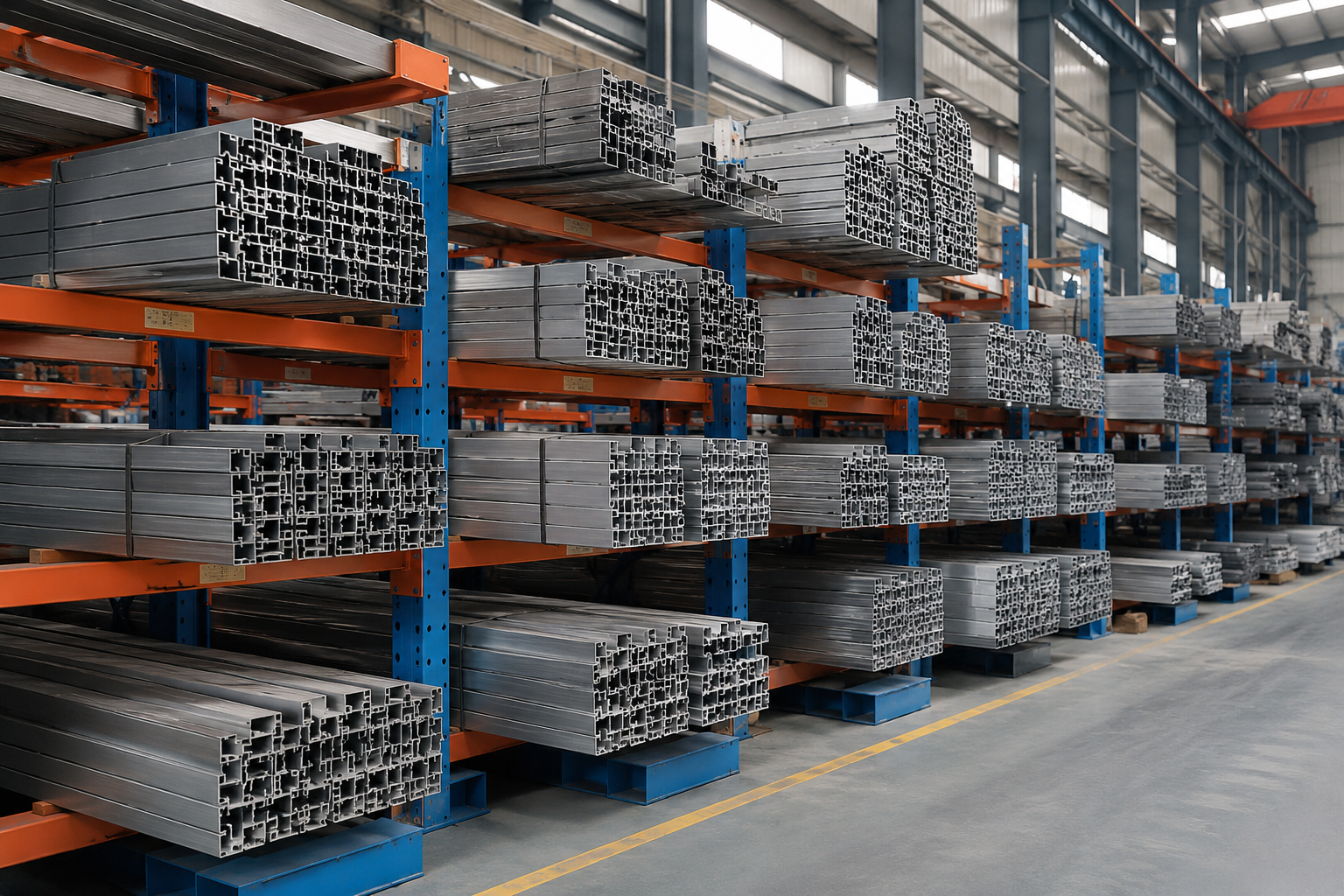
If you're a wholesaler or furniture factory procurement manager placing bulk orders, this article shows you how to verify that profiles physically fit your project constraints before shipment, using documented failure patterns from our customer complaint records.
What's The Difference Between Frame Profiles And Ground Tracks?
I received a complaint last year from a Vietnamese distributor who ordered 500 meters of what they thought were "glass door profiles," but the mounting hole positions didn't align with their floor installation plan. They had purchased frame profiles designed for wall mounting and tried to install them as ground tracks.
Frame profiles attach to vertical surfaces (walls, door frames) and bear horizontal loads—they hold the glass from the side. Ground tracks sit on floors and bear vertical loads—they support the glass from below.1 These are separate products with different slot positions, mounting hole patterns, and wall thickness distributions.
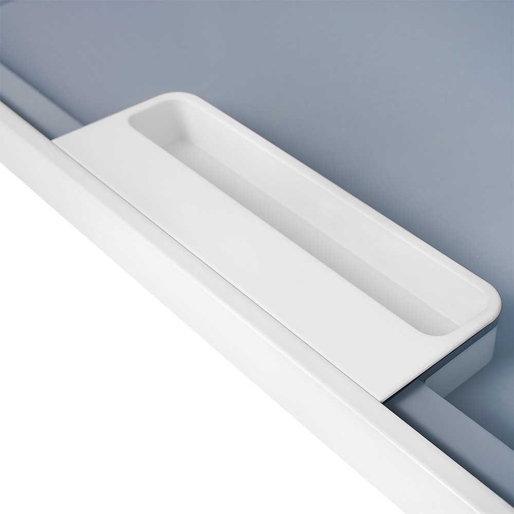
Frame profiles have slots positioned for side-insertion of glass panels, with mounting holes spaced for vertical attachment to walls or door frames. The wall thickness is concentrated on the back face where load transfers to the mounting surface. Ground tracks have bottom-facing slots with continuous channels for sliding mechanisms, with reinforced base sections to distribute floor pressure across wider contact areas.
When you tell suppliers "I need glass door profiles," they can't determine which product you need without knowing your installation method. Sliding doors typically require both ground tracks (for movement) and frame profiles (for side support). Hinged doors need frame profiles with different mounting hole patterns to accommodate hinge hardware. Fixed glass panels need frame profiles with no provision for moving parts.
Before requesting quotes, clarify: Will the glass slide horizontally along the floor? Will it pivot from a vertical frame? Will it remain fixed within a frame border? Each scenario requires different profile types that cannot substitute for one another during installation.
How Does Wall Thickness Determine Whether Profiles Survive Under Your Door Weight?
A Middle Eastern furniture factory contacted us after their profiles deformed within three months of installation in a commercial showroom. They had ordered profiles with 0.8mm wall thickness to reduce costs, but their glass doors measured 2.8 meters in height and opened 30-40 times daily. The profiles couldn't maintain structural integrity under that operational stress.
Wall thickness controls whether the profile bends or cracks under the combined load of glass weight, opening force, and operational frequency.2 Thinner walls reduce material cost but increase deformation risk—the cost savings disappear when you replace failed profiles or lose project credibility.
Wall Thickness Requirements By Door Specifications
| Door Height | Glass Weight Range | Minimum Wall Thickness | Expected Service Life |
|---|---|---|---|
| Under 2 meters | 15-25 kg | 0.8-1.0 mm | 2-3 years (residential) |
| 2-2.5 meters | 25-40 kg | 1.0-1.2 mm | 3-5 years (light commercial) |
| 2.5-3 meters | 40-60 kg | 1.2-1.5 mm | 5+ years (commercial) |
| Above 3 meters | 60+ kg | 1.5+ mm | Requires engineering calculation |
These ranges assume moderate opening frequency (10-20 cycles per day). High-traffic installations—retail storefronts, hotel lobbies, office buildings—need the next thickness tier up regardless of door height. Glass weight includes not just the panel itself but hardware attachments: handles, locks, closing mechanisms. A 2.3-meter door might seem to fit the 1.0mm category, but if you're installing commercial-grade hardware and expect 40+ daily cycles, you need 1.2mm profiles.
Wall thickness below specification doesn't fail immediately. The profile gradually deforms over weeks or months. First, you notice slight bending at the midpoint where load concentrates. Then the glass begins catching during sliding motion. Eventually, stress cracks appear near mounting holes or corner joints. By the time customers report problems, multiple installations have failed and your replacement costs exceed what you saved buying thinner profiles.
Verify wall thickness before placing bulk orders by requesting physical samples and measuring with calipers at multiple points—not just reading specification sheets. Some suppliers list nominal thickness but deliver profiles where actual measurement falls 0.1-0.2mm below stated values. That difference seems minor but becomes critical when profiles operate at their load limit.
Why Does Glass Thickness Create Installation Gaps If Slot Width Doesn't Match?
One of our wholesaler clients in Vietnam ordered profiles with 10mm slots for a project using 12mm glass. They assumed a 2mm gap wouldn't matter or could be filled with gaskets. During installation, they discovered the glass panels tilted inside the oversized slots, creating uneven gaps at top and bottom edges. Even after forcing the glass into position, it had lateral movement that made the doors unstable.
Slot width must match glass thickness within 2mm tolerance—either direction. Oversized slots let glass tilt and shift. Undersized slots prevent glass insertion or create force concentration points that crack panels during installation. Gaskets and sealants don't compensate for mismatched dimensions; they only seal matched assemblies.
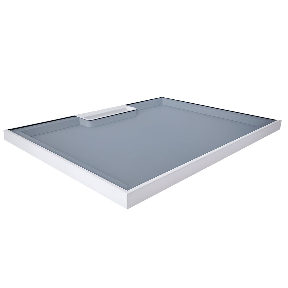
Glass panels aren't perfectly uniform in thickness. Manufacturing tolerance means 10mm glass measures 9.8-10.2mm at different points.3 If you order 10mm slot profiles, the minimum glass thickness (9.8mm) leaves a 0.2mm gap on each side, while maximum thickness (10.2mm) creates friction during insertion. This tolerance stacking is normal and acceptable. Problems occur when the base mismatch exceeds 2mm.
A 10mm slot with 12mm glass makes installation physically impossible without forcing, which cracks glass edges or bends profile lips. A 12mm slot with 10mm glass allows 1mm movement on each side—enough for the panel to tilt 2-3 degrees, creating visible gaps that collect dirt and compromise door stability. Customers often think they can fix this by adding thicker gaskets or weather stripping, but these materials compress under door weight and lose effectiveness within weeks.
Common glass thicknesses in furniture applications are 8mm, 10mm, and 12mm.4 Profiles are manufactured with corresponding slot widths: 8-9mm, 10-11mm, and 12-13mm. When requesting quotes, don't say "glass door profiles"—specify "profiles for 10mm glass" or whatever thickness your project uses. Suppliers can't recommend correct slot width without knowing actual glass specifications, and ordering wrong creates installation failures that aren't covered under quality warranties.
Verify slot width on physical samples before bulk production. Insert your actual glass (or sample of exact thickness) into the profile slot and check for fit—glass should slide with light resistance, no tilting, and no forcing required. If you're working with mixed glass thicknesses across one project, you need separate profile batches with matching slot widths.
How Does Installation Method Change Which Part Of The Profile Bears Load?
A furniture factory in the Middle East sent us photos of cracked profiles after installation. The damage pattern showed stress fractures near the top edge of frame profiles—unusual because we expected floor-mounted tracks to fail first under door weight. Investigation revealed they had used wall-mounted frame profiles in a floor-sliding installation, so the frame's thin upper edge bore downward pressure it wasn't designed to handle.
Floor-mounted tracks distribute vertical load across a wide base section. Wall-mounted frames transfer horizontal load through a narrow back section to mounting screws. Sliding doors apply shear forces during movement. Hinged doors concentrate rotational forces at hinge points. Each installation method creates different load patterns that require profiles engineered for those specific stress directions.
Load Distribution By Installation Type
| Installation Method | Primary Load Direction | Reinforced Profile Section | Failure Points If Mismatched |
|---|---|---|---|
| Floor sliding | Vertical compression | Wide base with internal ribs | Base cracks, slot deformation |
| Wall-mounted frame | Horizontal tension | Thick back wall, reinforced mounting holes | Mounting hole tears, back wall bending |
| Top-hung sliding | Suspension load | Upper channel with load-bearing lips | Upper channel separation, lip bending |
| Hinged pivot | Rotational shear | Local thickness at hinge points | Stress cracks radiating from hinges |
Wholesalers often order profiles based on door size without clarifying installation method. Suppliers assume the most common configuration—floor sliding—and ship profiles optimized for vertical load. If your project uses wall-mounted frames or top-hung systems, those profiles will fail prematurely even if wall thickness and slot width are correct. The material is strong enough, but the reinforcement is in the wrong locations.
Floor-mounted tracks have thick base sections, often with internal ribs or channels that spread weight across the floor contact area. The upper portion can be thinner because it only channels the glass, not supporting its full weight. Wall-mounted frames are opposite—thin or even open at the base, but thick at the back where mounting screws attach and load transfers to the wall. Using one in place of the other puts maximum stress on the weakest section.
When requesting quotes, describe your installation plan: "glass panels slide horizontally on floor tracks with wall-mounted side frames" or "hinged doors attached to vertical frames, no floor support." Suppliers need this information to confirm their stock profiles match your installation method, or to recommend modifications. Generic descriptions like "glass door profiles" don't communicate load requirements.
Top-hung systems deserve special attention because they reverse typical load direction—profiles suspend the full door weight from above rather than supporting from below.5 Standard floor track profiles lack the necessary upper channel strength and mounting provisions for hanging hardware. Attempting to adapt floor tracks to top-hung installations creates dangerous failure risks where the entire door assembly could detach.
What Surface Treatment Determines Whether Coating Survives Daily Use?
I've seen complaints where profiles looked perfect at delivery but showed wear marks, color fading, or corrosion spots within six months of installation. The aluminum itself hadn't failed, but the surface treatment couldn't withstand the friction, cleaning chemicals, or humidity in actual operating conditions. Customers assumed all "anodized" or "powder coated" profiles offered the same durability.
Anodization thickness and powder coating formulation determine whether surface finish withstands sliding friction, chemical cleaning, and environmental exposure over years of operation. Thin treatments meet visual quality standards but wear through to bare aluminum within months. Coating selection must match your project's operational environment, not just aesthetic preferences.
Anodization isn't a single process—layer thickness varies from 5 microns (decorative) to 25 microns (architectural/commercial grade). Sliding doors generate continuous friction between glass channels and profile slots. If anodization is only 5-8 microns thick, that friction wears through to bare aluminum in high-traffic installations within 3-6 months. The aluminum underneath oxidizes differently than the anodized layer, creating visible gray streaks along wear paths.6
Powder coating creates thicker surface layers but varies in hardness and chemical resistance based on resin formulation.7 Standard decorative powder coatings chip or scratch easily with metal-on-metal contact from door hardware. Commercial-grade formulations include harder resins and UV stabilizers that maintain appearance and protection under operational stress. You can't identify coating grade by visual inspection—it requires specification sheets stating coating thickness (minimum 60 microns for commercial) and hardness ratings.
Humid or coastal environments demand additional corrosion resistance beyond what standard surface treatments provide. We've handled complaints from Middle Eastern clients where profiles installed in humid climates showed corrosion pitting within one year despite having "anodized" finishes. Investigation showed the anodization was only 8 microns thick and wasn't sealed properly—moisture penetrated to the aluminum substrate and initiated corrosion from beneath the surface layer.
When specifying profiles, state your operating environment: "dry interior residential," "commercial with daily cleaning," "coastal humidity," or "high-traffic retail." Don't accept generic "anodized" or "powder coated" descriptions. Request minimum anodization thickness (15+ microns for commercial, 20+ for exterior or humid environments)8 or powder coating specifications (60+ micron thickness, 2H+ pencil hardness for commercial applications)9. Suppliers familiar with your market conditions can recommend appropriate treatments, but only if you communicate actual operating stress.
Surface treatment directly affects long-term cost. Profiles with inadequate coating require replacement years earlier than properly treated versions—the 15-20% price premium for commercial-grade surface treatment saves 100% replacement cost down the line. This is especially critical for projects where profile replacement requires disassembling entire door systems or where visible wear damages your reputation with end customers.
How Do You Verify Specifications Match Your Project Before Bulk Orders?
The most expensive selection mistakes happen between order placement and installation—after you've paid for bulk quantities but before discovering the profiles don't fit your project parameters. I've seen wholesalers receive 1,000+ meters of profiles that can't be installed because slot width, wall thickness, or mounting hole patterns don't match actual requirements.
Request physical samples that match your exact specifications: glass thickness, door height range, and installation method. Test-fit those samples with your actual glass and hardware before bulk production. Measure wall thickness at multiple points with calipers. Verify mounting hole positions align with your installation plans. These verification steps take one week but prevent losses that take months to resolve.
Sample testing isn't just visual inspection. You need to physically install the sample profile in a configuration that matches your project: insert glass of actual thickness, attach mounting hardware, simulate the full range of door motion. This reveals compatibility issues that don't show in specification sheets—glass that fits the slot but binds during sliding, mounting holes that align vertically but not horizontally with your frame spacing, profiles that look sturdy but flex under actual door weight.
Wall thickness measurement requires calipers and multiple measurement points. Don't measure only at profile ends where suppliers sometimes maintain full thickness. Measure at midpoints and near mounting holes where some manufacturers thin the wall to reduce material cost. A profile spec'd at 1.2mm might measure 1.15-1.18mm at critical stress points—acceptable tolerance—or 1.0-1.05mm if the supplier is cutting corners. That 0.15mm difference determines whether the profile survives your load requirements.
Verify surface treatment by requesting coating thickness reports or conducting basic durability tests on samples. For anodized profiles, some testing labs can measure layer thickness non-destructively10. For powder coatings, you can perform simple pencil hardness tests (pushing pencils of increasing hardness against the surface until one scratches through) to verify the coating meets minimum hardness specifications. These aren't comprehensive material tests, but they catch grossly substandard surface treatments before bulk orders.
Document your verification process with photos and measurements. If profiles arrive that don't match tested samples, you have evidence for quality disputes. Suppliers sometimes substitute different batches or grades between sample approval and bulk production—documentation proves what you approved versus what you received. This is especially important for international orders where inspection and returns involve significant time and cost.
Create a pre-order checklist: glass thickness confirmed in writing, slot width measured on physical sample, wall thickness verified at 3+ points, mounting hole pattern test-fitted with actual hardware, surface treatment specifications stated in purchase order, sample retained for batch comparison. Each checkpoint takes 10-30 minutes but prevents installation failures that cost thousands in replacement profiles, labor, and project delays.
Conclusion
Selecting glass door aluminum profiles isn't about finding the cheapest supplier or the highest quality material—it's about matching measurable specifications to your project's glass thickness, door weight, installation method, and operating environment before placing bulk orders.
"Nature's Load-Bearing Design Principles and Their Application in ...", https://pubmed.ncbi.nlm.nih.gov/39329566/. Structural engineering principles distinguish between vertical loads (compression forces directed downward) and horizontal loads (lateral forces), which require different material reinforcement patterns and mounting strategies. Evidence role: mechanism; source type: education. Supports: the distinction between vertical and horizontal load-bearing in structural applications. Scope note: This supports the general principle of load direction differences, though not specifically for aluminum door profiles ↩
"Progressive Failure Analysis of Thin-Walled Composite Structures ...", https://pmc.ncbi.nlm.nih.gov/articles/PMC7084992/. In thin-walled structures, wall thickness directly affects the section modulus and moment of inertia, which determine resistance to bending and local buckling under applied loads. Evidence role: mechanism; source type: education. Supports: the relationship between material thickness and resistance to bending or buckling under load. ↩
"[PDF] Structural Behavior Of Architectural Laminated Glass - Scholars' Mine", https://scholarsmine.mst.edu/context/civarc_enveng_facwork/article/3575/viewcontent/STRUCTURAL_BEHAVIOR_OF_ARCHITECTURAL_Laminated_Glass.pdf. Industry standards for flat glass production specify thickness tolerances that vary by nominal thickness and manufacturing method, typically ranging from ±0.2mm to ±0.5mm for common architectural glass products. Evidence role: statistic; source type: institution. Supports: typical manufacturing tolerances for architectural glass thickness. Scope note: Exact tolerances depend on glass type, manufacturing process, and applicable regional standards ↩
"Glass Thickness Guide", https://www.a1glassandmirror.com/glass-thickness-guide. Architectural and furniture applications typically employ glass panels in standardized thicknesses, with 6mm, 8mm, 10mm, and 12mm being widely available commercial sizes that balance structural requirements with manufacturing economics. Evidence role: general_support; source type: institution. Supports: common glass thickness ranges used in architectural and furniture applications. Scope note: This describes general industry practice rather than a mandated standard ↩
"Tensile, Compressive and Bending Stresses and Strains", https://www.setareh.arch.vt.edu/safas/007_fdmtl_14_tension_compression_and_bending_stresses_and_strains.html. Suspended systems subject structural members to tensile (pulling) forces as they support loads from above, while floor-supported systems experience compressive (pushing) forces, requiring different design considerations for connection details, material selection, and failure mode prevention. Evidence role: mechanism; source type: education. Supports: the structural difference between suspended and supported load conditions. Scope note: This addresses general structural principles rather than specific door profile requirements ↩
"Anodizing - Wikipedia", https://en.wikipedia.org/wiki/Anodizing. Natural aluminum oxidation produces a thin, porous oxide layer with a dull gray appearance, while anodized coatings create a thicker, more uniform oxide structure that can be sealed and colored, resulting in visible contrast when anodized surfaces wear through to the base metal. Evidence role: mechanism; source type: education. Supports: the difference in appearance between anodized aluminum and naturally oxidized aluminum. ↩
"[PDF] Powder Coatings Technology Update - US EPA", https://19january2017snapshot.epa.gov/sites/production/files/2016-01/documents/powdercoatingstechupdate.pdf. Powder coating typically produces film thicknesses of 50-100 microns, significantly thicker than anodized layers, with final properties including hardness, flexibility, and chemical resistance determined by the polymer resin system (epoxy, polyester, polyurethane, or hybrid formulations). Evidence role: mechanism; source type: education. Supports: how powder coating thickness and properties vary with formulation. ↩
"[PDF] Process Specification for the Anodizing of Aluminum Alloys - NASA", https://www.nasa.gov/wp-content/uploads/2023/03/prc-5006-current.pdf. Industry specifications for aluminum anodizing recommend minimum coating thicknesses based on service environment: 15-18 microns for interior commercial applications, and 20-25 microns for exterior or corrosive environments to ensure adequate corrosion protection and wear resistance. Evidence role: expert_consensus; source type: institution. Supports: recommended anodization thicknesses for different environmental exposures. Scope note: Specific requirements may vary by regional standards and application criticality ↩
"[PDF] Generic Testing and Quality Assurance - EPA Archive", https://archive.epa.gov/nrmrl/archive-etv/web/pdf/06_vp_powder.pdf. Commercial powder coating specifications commonly require minimum dry film thickness of 60-80 microns and pencil hardness ratings of 2H or higher to provide adequate protection and durability in high-use applications, as measured by standardized test methods. Evidence role: statistic; source type: institution. Supports: typical thickness and hardness specifications for commercial-grade powder coatings. Scope note: Specific requirements vary by application and may reference different testing standards ↩
"Coating thickness measurement | Helmut Fischer", https://www.helmut-fischer.com/applications/technology/coating-thickness-measurement. Non-destructive coating thickness measurement techniques include magnetic induction methods for coatings on ferrous metals and eddy current methods for non-conductive coatings on non-ferrous metals like aluminum, allowing accurate thickness determination without damaging the coating or substrate. Evidence role: mechanism; source type: education. Supports: non-destructive methods for measuring coating thickness on metal substrates. ↩